Work in progress matrix mixer.
5/07/2015
3/15/2015
Interesting repair work followup
I decided not to trace the Locobox delay after all. Seeing how the circuit most probably resembles other Japanese BBD (MN3005) delays from the era, for which schematics abound. I expect some 'delay-aficionados' will want to know exactly what makes a certain box tick and how it differs from others. In this case there seems to be a lot of rebranded releases of the same PCB..
I'm not one of those guys. I do love delays, just not the hype surrounding certain models. It's just not very interesting from a circuit design standpoint either, considering how noisy it is. Some of the noise can probably be attributed to ageing components and damaged semiconductors, but that isn't likely to be the only source. I'm guessing the effect is inherently noisy, and fixing that would require quite invasive modifications, lowering second hand price for the afficionados who want their vintage stuff original..
So this one goes back to the customer mostly unchanged and untraced.
The TS9DX DC jack was intermittent, fixed by having the joints re-soldered, so it was an easy repair. It's interesting to see how boardmounted hardware in theory shouldn't be any more susceptible to mechanical stress and damage than 'off board'-wired, but in theory this just doesn't seem to be the case. I guess tolerances explain most of it, but it makes me wonder.
Also, interesting to see the "Stinkfoot" mods, performed in 2004-09-11? Hej Andreas!
I'm not one of those guys. I do love delays, just not the hype surrounding certain models. It's just not very interesting from a circuit design standpoint either, considering how noisy it is. Some of the noise can probably be attributed to ageing components and damaged semiconductors, but that isn't likely to be the only source. I'm guessing the effect is inherently noisy, and fixing that would require quite invasive modifications, lowering second hand price for the afficionados who want their vintage stuff original..
So this one goes back to the customer mostly unchanged and untraced.
The TS9DX DC jack was intermittent, fixed by having the joints re-soldered, so it was an easy repair. It's interesting to see how boardmounted hardware in theory shouldn't be any more susceptible to mechanical stress and damage than 'off board'-wired, but in theory this just doesn't seem to be the case. I guess tolerances explain most of it, but it makes me wonder.
Also, interesting to see the "Stinkfoot" mods, performed in 2004-09-11? Hej Andreas!
![]() |
| Repaired ('Stinkfoot'-modded) TS9DX |
3/05/2015
Interesting repair work
A friend of mine asked me to fix his '"Locobox" Analog Delay' and a 'Ibanez TS9DX Turbo Tube Screamer'. I rarely come across pedals I haven't already heard of but the "Locobox" brand is all new to me. It's apparently a somewhat obscure Japanese brand. This particular model is probably 1970's vintage. I just might trace the circuit but I'm already pretty sure it'll be very close, if not identical to other Japanese brands from the era. We'll see.
![]() |
| Arty Locobox Analog Delay gutshot |
![]() |
| Locobox Analog Delay and TS9DX |
1/15/2015
Circuit testing and debugging
Everything fired up first go. The channel boards contain the PLL, VCO, waveshaper, ringmod, VCA, lock indicator and various related electronics. There are two identical channel boards, capable of operating independently from each other, but really designed with cross-modulation in mind. Each board is controlled from a 8-bit parallel data bus. Many features are jumperable the board is laid out for easy experimentation with features. There are so many possible configurations! Testing everything as a complete unit is difficult due to the sheer complexity of the PCB interconnect wiring and front panel control stuff. So I've been breaking it down into smaller parts, "divide and conquer".
![]() |
| One of the two 'channels' near completion. |
![]() |
| Digital control board, PIC goes in the empty socket. |
![]() |
| Two identical 'channel' boards. |
Etiketter:
Harmonizer,
MCU,
Octaver,
PLL,
Synth
Analog Harmonizer/Octaver PCBs
Lots of progress has been made during the last 6 months.
Design finalized, circuit prototyped, PCBs designed and manufactured,
components fitted, circuit tested and debugged (partly still in progress) ..
Some of the pre amp and fundamental extraction circuitry is built by hand on perfboard or breadboards. The remaining boards, 3 double-sided and 1 single-sided, are all done.
Making your own boards like this is hardly worth it considering how relatively easy it is to have a board house make the PCBs for you. However, buying this many boards from a fab house would be pretty expensive, especially when I probably won't bother with more than one unit. So in this case, a single run, prototype through hole.
Some photos of the etching process;
![]() |
| Sample of the PCB designs. |
![]() |
| Developed PCB. |
![]() |
| Etching in a etching tank. |
![]() |
| Preview of the result. |
![]() |
| All PCBs etched. |
Etiketter:
Harmonizer,
Octaver,
PLL,
Synth
5/20/2014
Next Distortion X
Got one of these in for repairs. CMOS inverter overdrive made in the early 80's.
Seems somewhat rare, can't find any schematics or such. So I traced it out.
Some values are missing but I'm fairly sure it's correct. Interesting circuit design.
That weird 5-terminal potentiometer is crazy worn down, good luck finding a replacement..
Seems somewhat rare, can't find any schematics or such. So I traced it out.
Some values are missing but I'm fairly sure it's correct. Interesting circuit design.
That weird 5-terminal potentiometer is crazy worn down, good luck finding a replacement..
![]() |
| Kitty cameo |
![]() |
| Distortion X |
![]() |
| Distortion X PCB top |
![]() |
| Distortion X PCB bottom |
![]() |
| Distortion X schematic |
Etiketter:
distortion x,
next,
schematic,
trace
12/26/2013
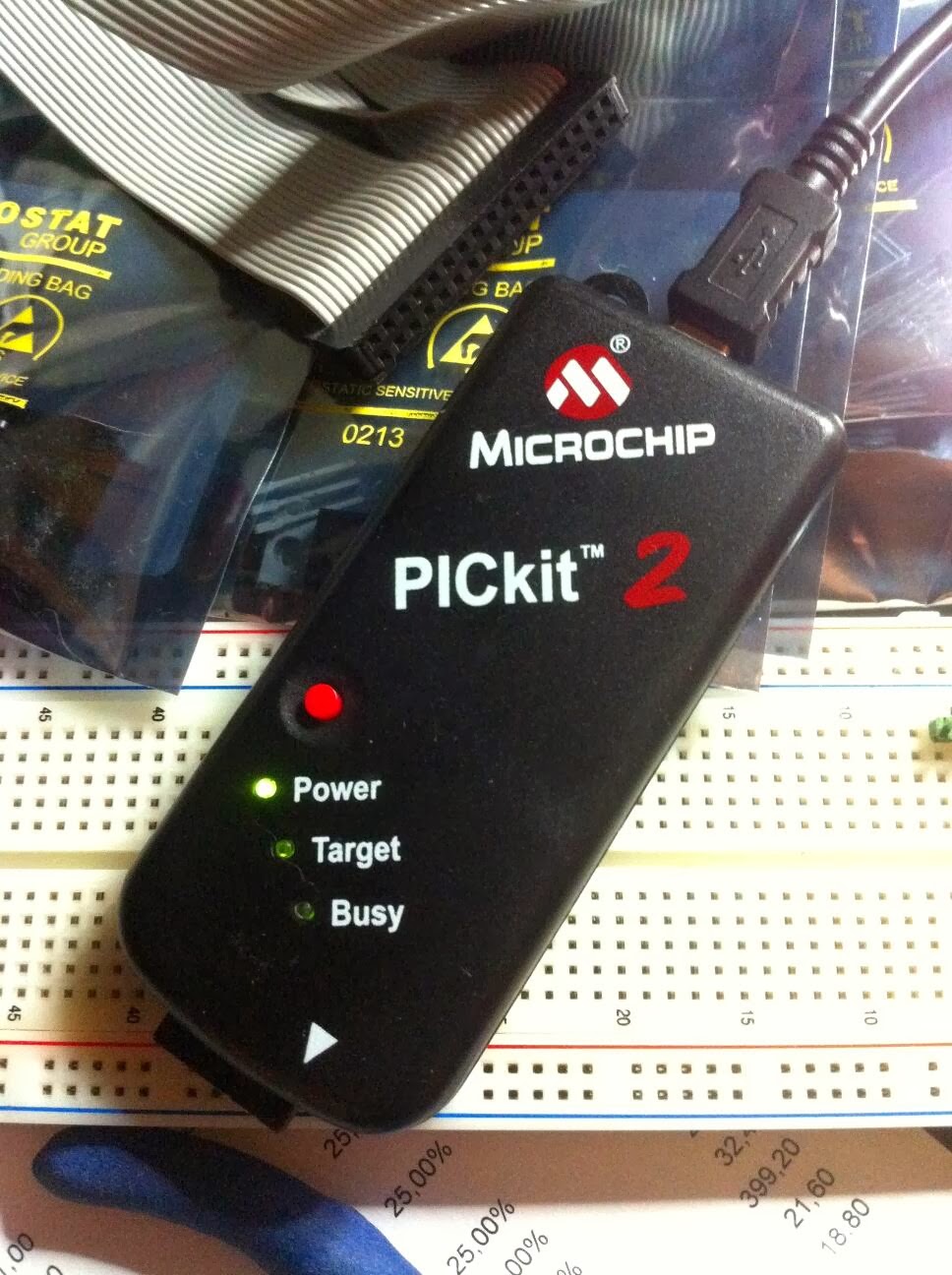
Microcontrollers
Coding assembler is a pain.
![]() |
| PICkit 2 programmer/debugger |
10/04/2013
State of Guitar-Synthy-Monstrosity -affairs
![]() |
| Input stage, compressor, filtering & fundamental extractor. |
![]() |
| Overview: Input stage bottom left. Input/output -thingy top left. Channel #1 top right. Channel #2 bottom right. |
Etiketter:
Breadboard,
Harmonizer,
Octaver,
PLL,
Prototype,
Synth,
WIP
9/27/2013
8/23/2013
Guitar 'synth' Update
Debugged the new waveshaper circuitry. Works very well using a technique rarely (if ever) seen in audio stuff. Also added a simple ring modulator a'la Korg MS-20 which works very well with the oscillators footswitchable 'note hold'-function.
Some of the 'typical' synth waveforms didn't sound interesting enough and got replaced by my own weirdo concoctions..
![]() |
| Weirdwaves™ |
Etiketter:
Harmonizer,
Octaver,
PLL,
Synth
7/18/2013
Analog Harmonizer/Octaver
Three out of five 'voices' almost done.
Huge breadboard is huge.
Also; circuit completely redesigned..
4/09/2013
10/31/2012
Voltage Controlled Multimode Filter
Commissioned build and still a work in progress.
Voltage controlled state variable filter with all the bells and whistles.
The filter can be controlled by playing dynamics (envelope follower), voltage controlled LFO/Sample&Hold or manually with a knob/external expression pedal. Also has a buffered effect loop, wet/dry mix and active volume control.
The envelope follower circuit is pretty complex, at least in the stompbox world..
Frequency specific somewhat log. amplification/attenuation, full wave rectification..
Attack and release times are completely independent and non-interactive. The release is linear (as opposed to the 1/2piRC discharge), which means the effective filtering is more effective and any residual 'ripple' or AC components in the envelope voltage is reduced.
However, the change in release time for a given rotation of the release-knob is exponential, which means the response seems natural and useful.
It has dawned on me that voltage controllable everything is way beneficial..
I've spent a lot of time with the sidechain and I'm very proud of the result.
The LFO/Sample&Hold rate can be modulated by the envelope follower. The initial frequency is set with a knob. Another knob then sets the amount of modulation. Set fully CCW, the rate decreases from the initial frequency when picking harder. Set fully CW the rate increases from the initial frequency when picking harder. And set to the 12'oclock position the modulation is disabled. Other controls work in a similar way. Switches < Pots.
All analog. 22 ICs, 28 Transistors.
Voltage controlled state variable filter with all the bells and whistles.
The filter can be controlled by playing dynamics (envelope follower), voltage controlled LFO/Sample&Hold or manually with a knob/external expression pedal. Also has a buffered effect loop, wet/dry mix and active volume control.
The envelope follower circuit is pretty complex, at least in the stompbox world..
Frequency specific somewhat log. amplification/attenuation, full wave rectification..
Attack and release times are completely independent and non-interactive. The release is linear (as opposed to the 1/2piRC discharge), which means the effective filtering is more effective and any residual 'ripple' or AC components in the envelope voltage is reduced.
However, the change in release time for a given rotation of the release-knob is exponential, which means the response seems natural and useful.
It has dawned on me that voltage controllable everything is way beneficial..
I've spent a lot of time with the sidechain and I'm very proud of the result.
The LFO/Sample&Hold rate can be modulated by the envelope follower. The initial frequency is set with a knob. Another knob then sets the amount of modulation. Set fully CCW, the rate decreases from the initial frequency when picking harder. Set fully CW the rate increases from the initial frequency when picking harder. And set to the 12'oclock position the modulation is disabled. Other controls work in a similar way. Switches < Pots.
All analog. 22 ICs, 28 Transistors.
![]() |
| Filter block diagram |
Etiketter:
Bass,
Envelope,
Filter,
SampleandHold
7/10/2012
Guitar synth sound sample
Quick and dirty recording of the guitar synth prototype.
The prototype is very sensitive and noisy on the breadboard, so recording is somewhat fiddly. I go through random combinations of interval, octave and waveform. One of the channels is fixed at unity octave.
One channel set at unity interval, unity octave and sawtooth. The other channel is set at squarewave, unity octave. I go through all the intervals.
The prototype is very sensitive and noisy on the breadboard, so recording is somewhat fiddly. I go through random combinations of interval, octave and waveform. One of the channels is fixed at unity octave.
One channel set at unity interval, unity octave and sawtooth. The other channel is set at squarewave, unity octave. I go through all the intervals.
7/07/2012
Analog guitar synth update
My PLL-based harmonizer/octaver/'guitar-synth' has come a long way.
The design goals and circuit has evolved during development.
My current prototype has two separate channels.
Each channel has it's own set of interval, octave and waveform-selectors.
- Available intervals: unison, maj 3rd, perfect 4th, perfect 5th and a major 6th.
- The octave-selector has six positions: -2, -1, unison, +1, +2, +3.
- The waveform-selector also has six positions.
Five waveforms are implemented in the prototype: square, triangle, saw, stepped triangle and stepped saw. I haven't yet fully decided on the last waveform. I'm contemplating pulsewave with adjustable (and/or modulated) pulsewidth.
The synthesized waveforms are sent to a voltage controlled amplifier, which is controlled by the raw guitar signal. This means playing dynamics are retained, and synthesized notes decay naturally, along with the guitar signal. It also eliminates stuttering and glitches at the end of notes.
Each channel also has a 'hold'-function, which when activated holds the note played indefinitely. The held note can be set to follow the guitar amplitude, or remember the amplitude at the time of activation, and stay there.
Lastly, the two channel outputs and the original guitar signal is sent to a mixer.
A 'balance'-knob sets the relative amplitude of the two channels. And a wet/dry-knob adjusts the amount of raw guitar input vs. synthesized signals.
I've had so much fun playing with the prototype.
The possible combinations of intervals, octaves and waveforms makes it very versatile.
Next up is some finishing touches and optimization(/minimization..).
The circuit is very complex, with a huge number of components. All of which could be replaced with just a single microcontroller. But what is the fun in that?
The design goals and circuit has evolved during development.
My current prototype has two separate channels.
Each channel has it's own set of interval, octave and waveform-selectors.
- Available intervals: unison, maj 3rd, perfect 4th, perfect 5th and a major 6th.
- The octave-selector has six positions: -2, -1, unison, +1, +2, +3.
- The waveform-selector also has six positions.
Five waveforms are implemented in the prototype: square, triangle, saw, stepped triangle and stepped saw. I haven't yet fully decided on the last waveform. I'm contemplating pulsewave with adjustable (and/or modulated) pulsewidth.
The synthesized waveforms are sent to a voltage controlled amplifier, which is controlled by the raw guitar signal. This means playing dynamics are retained, and synthesized notes decay naturally, along with the guitar signal. It also eliminates stuttering and glitches at the end of notes.
Each channel also has a 'hold'-function, which when activated holds the note played indefinitely. The held note can be set to follow the guitar amplitude, or remember the amplitude at the time of activation, and stay there.
Lastly, the two channel outputs and the original guitar signal is sent to a mixer.
A 'balance'-knob sets the relative amplitude of the two channels. And a wet/dry-knob adjusts the amount of raw guitar input vs. synthesized signals.
I've had so much fun playing with the prototype.
The possible combinations of intervals, octaves and waveforms makes it very versatile.
Next up is some finishing touches and optimization(/minimization..).
The circuit is very complex, with a huge number of components. All of which could be replaced with just a single microcontroller. But what is the fun in that?
![]() |
| Prototype circuit. Lots of chips. |
Etiketter:
Harmonizer,
Octaver,
PLL,
Synth
1/29/2012
1/13/2012
1/12/2012
11/19/2011
Captains log..
Stardate 65437.6
Long time, no updates.
School and miscellaneous annoyances have done a great job of keeping me distracted. I'm currently working on a "analogue" harmonizer/octaver based on a phase locked loop. I'm aiming for a ridiculously high knob-count on this one. Maybe it's time to go modular..
The prototype circuit tracks the guitar surprisingly well and I'm sure tracking will be even better once I implement and test the complete circuit with more efficient signal conditioning.
Two parallel sections with independent controls will allow dual harmonies/octaves. E.g. a perfect 5th, two octaves up and a harmonic 7th, one octave down simultaneously.
I currently get square wave outputs but the plan is to extend the available waveforms. Using example circuits from the CMOS cookbook, I've been able to generate a 'sine' wave. The scope picture shows the raw output from the first trials. After low pass filtering the signal, the blocky stair steps disappear.
No scope photos of the current circuit, you'll have to take my word..
Two parallel sections with independent controls will allow dual harmonies/octaves. E.g. a perfect 5th, two octaves up and a harmonic 7th, one octave down simultaneously.
I currently get square wave outputs but the plan is to extend the available waveforms. Using example circuits from the CMOS cookbook, I've been able to generate a 'sine' wave. The scope picture shows the raw output from the first trials. After low pass filtering the signal, the blocky stair steps disappear.
No scope photos of the current circuit, you'll have to take my word..
![]() |
| Raw digital 'sine' wave. Looks surprisingly good when LP-filtered. |
3/28/2011
Prenumerera på:
Inlägg (Atom)


